Bowling Sign Tutorial
Introduction
This tutorial is designed to help you become familiar with the BobART features in an assembly. Follow this tutorial along with the other Emboss tutorials to learn more about the BobART Emboss features. The following features will be used to create the model:
- Emboss Swept - Add
- Emboss from Component - Merge High
- Emboss Regular - Merge Low
- Emboss Regular - Merge High
- Emboss Regular - Subtract
- Emboss 2 Rail Sweep - Merge High
- Loading an Image
- Vectorizing an Image
- Saving a Component
- Emboss from Component - Add
Example File
The part file for this tutorial is available for download at: http://www.bobcad.com/helpfiles.
If you are connected to the Internet, you can click the link provided
to download and save the BowlingSignAssembly.zip file. After downloading the zip file, extract
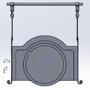
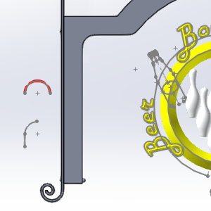
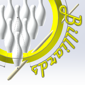
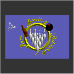
the files on your system in a location of your choosing. In the images below, you will see what we are working towards with our BobART creation steps. 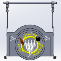


Part 1) Open the Example File
-
In the File menu, click Open.
The Open dialog box is displayed. -
Select the folder in which you saved the example files.
-
Select BowlingSignAssembly.sldasm, and click Open.
The file is opened and the geometry is displayed in the graphics area.
Important: If, when the assembly is open, the parts in the Feature Manager Design Tree show an ![]() icon, right-click
icon, right-click ![]() BowlingSignAssembly at the top of the Feature Manager Design Tree, and select Set Lightweight to Resolved. The part icons will then show an
BowlingSignAssembly at the top of the Feature Manager Design Tree, and select Set Lightweight to Resolved. The part icons will then show an ![]() icon, and you will then have access to the part features.
icon, and you will then have access to the part features.
Part 2) Adjust the Visibility of the Model
In order to see the sketches we are building the BobART model from, we hide the MainBoard component.
Note: The following step is not possible if your assemblies opens with lightwight components. If the MainBoard feature has a ![]() icon in front of it, first right-click the feature and select
icon in front of it, first right-click the feature and select ![]() Set to Resolved. This will allow you access to all the data in the feature. Once this is done, you will be able to accomplish Part 2.
Set to Resolved. This will allow you access to all the data in the feature. Once this is done, you will be able to accomplish Part 2.
- In the Feature Manager Design Tree, expand MainBoard.
- With MainBoard expanded, right-click Boss-Extrude1 and select Hide.
The MainBoard is hidden.
Part 3) Beginning an Emboss Model
In order to create a feature, a coordinate system must be associated with the Emboss Model, and stock must be set up. By attempting to create an emboss feature without doing this, we force the system to initiate those dialogs.
Create the Emboss Swept - Ring - Add
-
In the
 BobART Manager tab, right-click
  Emboss
Model, and click Emboss Swept.
Emboss
Model, and click Emboss Swept.
The Emboss Model Origin dialog opens in the Property Manager.
The Emboss Model Origin dialog is looking for a coordinate system to associate the BobART model with.
Associate a Coordinate System
- In the Design Tree, under the MainBoard, select the Front Plane.
The Front Plane is added to the Coordinate System list. - Click
 (Ok).
(Ok).
The Stock Parameters dialog box opens.
Set the Stock Parameters
-
In the Origin group, set the X value to -24.0000, and set the Y value to -16.0000.
- In the Model
Size group, set the X
value to 48.0000, and set the
Y value to 32.0000.
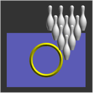
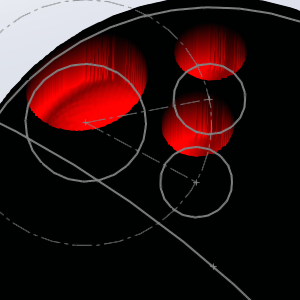
Note: The resolution updates automatically as the size is updated. The Resolution will improve the quality of the model, but also increase the size of the file, and the amount of time it takes to regenerate the surface.
A portion of the emboss, which will created at the end of the tutorial is used to illustrate the point. The image on the left shows stock with a resolution of 21, while the image on the right shows stock with a resolution of 86.

Normally, since ultra fine details will not be visible on the final machined part, stock with a higher resolution is not really needed. However, if it is wanted, wait until the model is complete and adjust the resolution at the end. This will keep regeneration times low during the creation of the model.
- Select the
 Remove Non-Emboss Area check box.
This option will remove all portions of the stock that are not affected by an emboss feature. Those portions will, however, remain visible until the first time the stock is regenerated, allowing you to confirm the proper size and placement of the stock. -
Click OK.
The Emboss dialog box opens.
Part 4) Create the Ring
The ring that circles the bowling pins is created by using an Emboss Swept with the Add application type selected.
Set the Feature Parameters
-
In the Emboss Attributes group, change the Name to Ring.
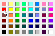
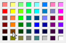
- Click Color.
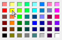
The Color dialog appears. - Select yellow.
- Click OK.
The Color dialog disappears. -
Click the Cross Section arrow, and select Line.
- In the Height box, type
1.0000.
Leave the Slope Angle at 45.0000.
Leave the Application Type to Add. This will cause the emboss to be added to the stock surface. - In the Fast Edit group, set the Base Height to 0.7500.
Since our Emboss Model is associated with the Front Plane of the MainBoard, and since the Front Plane is in the center of the MainBoard, we need to adjust the base height so our emboss model is on the surface of the MainBoard, and not inside of it. - Click OK.
The stock is visible.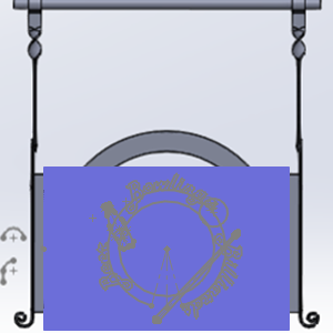
Notice the stock does not quite reach to the top of the arc. Since none of our intended design will go that high, this is fine.
Select Feature Geometry
-
Next to
 Ring - Add, click
  to expand the feature.
 - Under Ring - Add, right-click

 Geometry,
and select
Re/Select.
Geometry,
and select
Re/Select.
The Select Geometry for Art Item dialog opens in the Property Manager. -
In the graphics area, select the inner circle geometry as shown next.

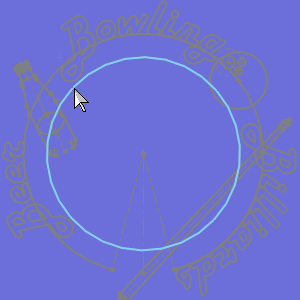
The geometry is added to the Re/Select Geometry list.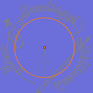
- To confirm the selection, click
 (OK) in the Property Manager.
Generate the Emboss Model
-
Right-click
 Emboss Model, and select Regenerate.
The body is now embossed and appears as shown next.
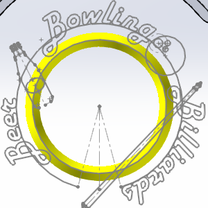
Notice the rest of the stock is gone leaving only the embossed area. This is because we have the Remove Non-Emboss Area check box in the Stock Parameters selected.
Part 5) Utilizing a Component - Bowling Pins
Using a component in BobART is really just importing an STL and adjusting its scale and position. In this case we utilize an STL of bowling pins setup in formation and use the Merge High application type.
Insert the Feature and Select the Component
-
Right-click
Emboss
Model, and click Emboss from Component.
The Open dialog appears. - Navigate to the folder in which you saved the
example files, and select, BowlingPins.stl.
- Click Open.
The Create Emboss from Component dialog appears with the current model visible in the open GL window.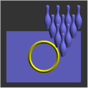
Set the Feature Parameters
-
Change the Name to Pins.
- Click Color,
select white, and click OK.

- In the Component Size group, set the X Size to 13.0000.
The component is resized.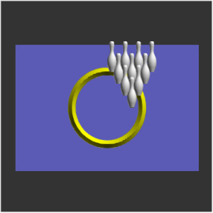
- Under Application Type, change the type to Merge High.
- In the Origin group, change the values to:
X: = -6.5000
Y: = -11.0000
Z: = -0.6800
- In the Zoom Fit group, click Component.
The window zooms in on the component.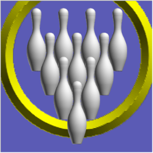
Notice we have the pins centered properly with the lead pin overlapping the ring. - Click OK.
The dialog disappears.
Regenerate the Emboss Model
-
Right-click
Emboss
Model, and select Regenerate.
The component is now visible on the Emboss Model.
Part 6) Embossing the Text : Step 1
Since portions of the text overlap the ring we created, and since we would like the overlapping portion to stand out a little more, we do the text in two steps. In this step we use the Merge Low application type to take a bite out of the ring.
Insert the Feature and Set the Parameters
-
Right-click
Emboss
Model, and click Emboss Regular. -
Change the Name to Words.
- Click Color,
select yellow, and click OK.
-
In the Cross Section group, leave Convex ARC as the selected cross section, but update the Radius to 0.5000.
-
Click the Application Type arrow, and click Merge Low.
- In the Fast Edit group, change the Base Height to 1.0000.
- Click OK.
Select Feature Geometry
- Expand the Words - Merge Low feature, right-click Geometry,
and click
Re/Select.
-
In the graphics area, select the geometry for the words.
The geometry is added to the Re/Select Geometry list.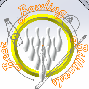
- Click (OK).

Regenerate the Emboss Model
-
Right-click
Emboss
Model, and click Regenerate.
The emboss model is updated.
Zoom into the portions of the model where the capital B's overlap the ring, and notice the small notches we created on the ring emboss.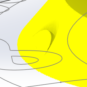
Part 7) Embossing the Text : Step 2
With the portions of the ring removed, we now repeat step 1 and replace the application type with Merge High.
- Repeat the steps of Part 7, but change the Application Type to Merge High.
With the Emboss Model regenerated, the view of the above area should now appear as seen in the image below.
Part 8) Suppress the Previous Feature
Suppressing features can be useful when create embossed models. In this case we want to test how the model would look without a certain feature.
- Right-click
 Words - Merge Low, and select
Suppress/Unsuppress.
Words - Merge Low, and select
Suppress/Unsuppress.
The name is grayed out. - Right-click Emboss
Model, and click Regenerate.
The emboss model is updated.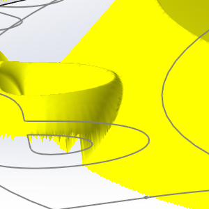
For comparison, an image of the same feature is shown using the Merge Low on the left, and having it suppressed on the right.
Part 9) Unsuppress the Previous Feature
- Repeat the steps of Part 9 to return the model to its original state.
Part 10) Creating the Bowling Ball - Step 1
For the bowling ball, we use the same method as we did with the text. Step 1 will remove a portion of the ring with the Merge Low application type, and the following step will create the bowling ball with the Merge High application type. We use a convex arc with the same radius as the bowling ball.
Insert the Feature and Set the Parameters
-
Right-click
Emboss
Model, and click Emboss Regular. -
Change the Name to Ball.
- Click Color,
select black, and click OK.

-
Leave theCross Section set to Convex ARC, but set the Radius to 2.7500.
-
Click the Application Type arrow, and click Merge Low.
- In the Fast Edit group, set the Base Height to 0.7500.
- Click OK.
Select Feature Geometry
-
Under
Ball - Merge Low, right-click Geometry,
and click
Re/Select. - In the graphics area,
select the geometry that represents the bowling ball as shown next.

The geometry is added to the list.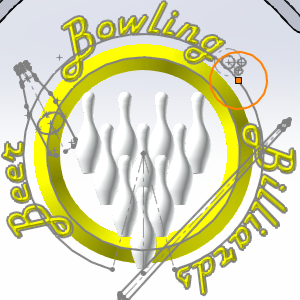
- Click (OK).

Regenerate the Emboss Model
-
Right-click
Emboss
Model, and click Regenerate.
Part 11) Creating the Bowling Ball - Step 2
With the portions of the ring removed, we now repeat step 1 and replace the application type with Merge High.
- Repeat the steps in Part 11, but set the Application Type to Merge High.
With the Emboss Model regenerated, the Emboss Model show appear as seen below.
Part 12) Creating the Thumb Hole
For this, and the following feature, we use a custom cross section and the Subtract application type to remove material in order to create the holes in the bowling ball.
Insert the Feature and Set the Parameters
-
Right-click
Emboss
Model, and click Emboss Regular. -
Change the Name to Thumb Hole.
- Click Color,
select red, and click OK.
-
Set theCross Section to Custom.
-
Click the Application Type arrow, and click Subtract.
- Click OK.
Select Feature Geometry
-
Under
Thumb Hole - Subtract, right-click Geometry,
and click
Re/Select. - In the graphics area,
select the geometry seen below.

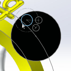
The geometry is added to the list.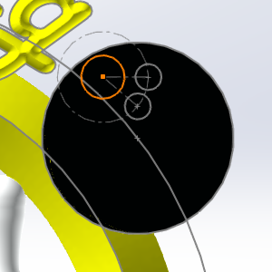
Note: The other two finger holes could actually be selected in this feature as well. In this tutorial we separate the like holes into two features so they can be handled differently if we so choose. Feel free to select all three holes at once. If you do, skip part 13 and move to part 14.
- Click (OK).

- Under Thumb Hole - Subtract, right-click Cross-Section Geometry,
and click
Re/Select.
- In the graphics area,
select the geometry seen below.

The geometry is added to the list.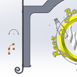
- Click (OK).
Regenerate the Emboss Model
-
Right-click
Emboss
Model, and click Regenerate.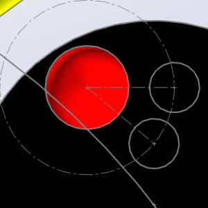
The hole is cut.
Part 13) Creating the Finger Holes
Insert the Feature and Set the Parameters
-
Right-click
Emboss
Model, and click Emboss Regular. -
Change the Name to Finger Holes.
- Click Color,
select red, and click OK.
-
Set the Cross Section to Custom.
-
Click the Application Type arrow, and click Subtract.
- Click OK.
Select Feature Geometry
-
Under
Finger Holes - Subtract, right-click Geometry,
and click
Re/Select. - In the graphics area,
select the geometry seen below.

The geometry is added to the list.
- Click (OK).

- Under Finger Holes - Subtract, right-click Cross-Section Geometry,
and click
Re/Select.
- In the graphics area,
select the geometry seen below.
The geometry is added to the list. - Click (OK).
Regenerate the Emboss Model
-
Right-click
Emboss
Model, and click Regenerate.
The holes are cut.
Part 14) Embossing the Cue
The cue is created with a 2 Rail Sweep and the Merge High application type will be used so that it goes through the ring.
Insert the Feature and Set the Parameters
-
Right-click
Emboss
Model, and click Emboss 2 Rail Sweep.
The 2 Rail Sweep dialog appears. -
Change the Name to Cue.
- Click Color.
The Color dialog appears. - Click Define Custom Colors >>.
The dialog expands. - Set the RGB values to Red: 211, Green: 202, Blue: 171, and click OK.
-
Click the Application Type arrow, and select Merge High.
- In the Fast Edit group, set the Base Height to 1.0000.
- Click OK.
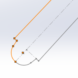
Select the Geometry for Rail 1
-
Under
Cue - Merge High, right-click Rail
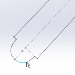
1-Geometry, and click Re/Select. -
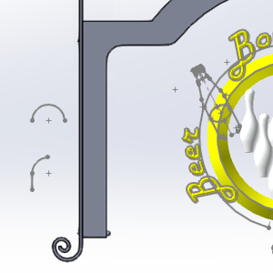
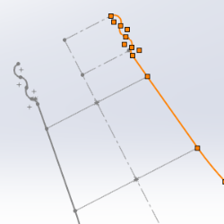
In the graphics area, select the geometry that represents one side of the cue as follows.

- Click OK.
Take note of the chain direction. In this case, the direction of the chain does not matter, as long as each chain is going the same direction.
Select the Geometry for Rail 2
-
Under
Cue - Merge High, right-click Rail
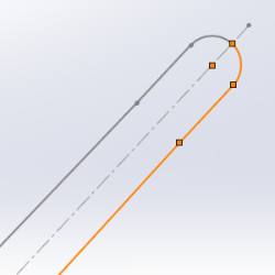
2-Geometry, and click Re/Select. -
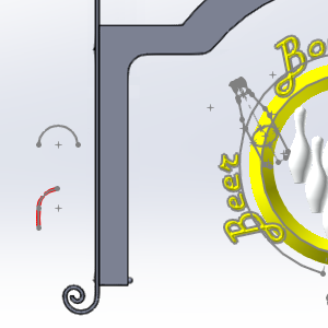
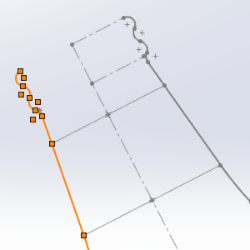
In the graphics area, select the geometry that represents the other side of the cue as follows.

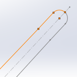
- Click OK.
Take note of the chain direction. In this case, the direction of the chain does not matter, as long as each chain is going the same direction.
Tip: To reverse the chain direction, right-click the Rail Geometry (or Cross-Section Geometry) item, and click Reverse Direction.
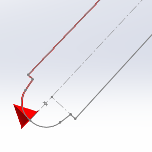
Select the Geometry for the Cross Section
-
Under
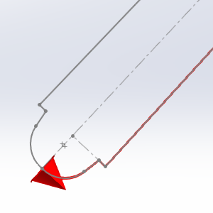
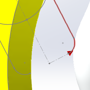
Cue - Merge High, right-click Cross-Section Geometry -1, and click Re/Select. -
In the graphics area, select the geometry as follows.

- Click OK.
Regenerate the Emboss Model
- Right-click Emboss
Model, and click Regenerate.

Tip: Notice the image on the right, shows the cue with its components separated by realistic colors. This was done by splitting the geometry of the cue into separate 2 Rail Sweep features, one for each color. While this does not change the surface, and therefore does not change the final machined product, it can be a nice touch when presenting a visual representation of the final product to a customer.
Part 15) Creating the Bottle
Just like the cue, the bottle is created with a 2 Rail Sweep, and the Merge High application type.
Insert the Feature and Set the Parameters
- Right-click Emboss Model, and click Emboss 2 Rail Sweep .
The 2 Rail Sweep dialog appears. - Change the Name to Bottle.
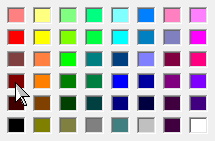
- Click Color,
select brown, and click OK.
- Click the Application
Type arrow, and select Merge High.
- In the Fast Edit group, change the Base Height to 1.0000.
- Click OK.
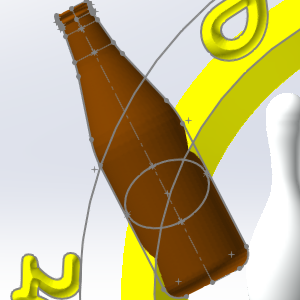
Select the Geometry for Rail 1
-
Under
Bottle - Merge Low, right-click Rail
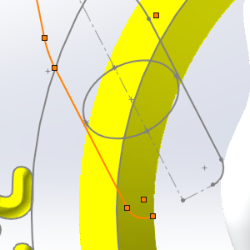
1-Geometry, and click Re/Select. -
In the graphics area, select the geometry that represents one side of the bottle as follows.

- Click OK.
Take note of the chain direction. In this case, the direction of the chain does not matter, as long as each chain is going the same direction.
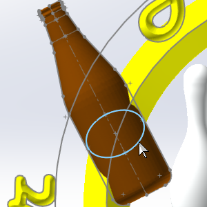
Select the Geometry for Rail 2
-
Under
Bottle - Merge Low, right-click Rail
2-Geometry, and click Re/Select. -
In the graphics area, select the geometry that represents the other side of the bottle as follows.

- Click OK.
Take note of the chain direction. In this case, the direction of the chain does not matter, as long as each chain is going the same direction.
Tip: To reverse the chain direction, right-click the Rail Geometry (or Cross-Section Geometry) item, and click Reverse Direction.
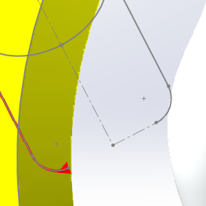
Select the Geometry for the Cross Section
-
Under
Bottle - Merge High, right-click Cross-Section Geometry -1, and click Re/Select. -
In the graphics area, select the geometry as follows.
- Click OK.
- Right-click Emboss
Model, and click Regenerate.

Tip: Notice the yellow ring is overlapping our bottle slightly, this can be prevented by first creating a Merge Low feature for our bottle, as we did with the lettering. Since this almost looks as if our ring is gripping our bottle, which is pretty cool, it will be left as is.
Part 16) Adding the Label to the Bottle
A simple emboss regular is used with the Add application type to add the material to the bottle where the labels would be.
Insert the Feature and Set the Parameters
-
Right-click
Emboss
Model, and click Emboss Regular. -
Change the Name to Label.
- Click Color,
select maroon, and click OK.
-
In the Cross Section group, leave Convex ARC as the selected cross section, but set the Radius to 0.2000.
-
Leave the Application Type, on Add.
- Click OK.
Select Feature Geometry
- Under Label - Add, right-click Geometry,
and click
Re/Select.
-
In the graphics area, select the geometry for the labels on the bottle, as seen below.

The geometry is added to the Re/Select Geometry list. - Click (OK).

Regenerate the Emboss Model
-
Right-click
Emboss
Model, and click Regenerate.
The emboss model is updated.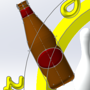
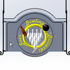
Part 17) Adjust the Visibility of the Part
In this part, the Main Board is made visible again, and the sketches we used to create the emboss model are hidden.
- In the Feature Manager Design Tree, expand MainBoard.
- With MainBoard expanded, right-click Boss-Extrude1 and select Show.
The MainBoard is shown. - Hold Ctrl, and select each of the Sketches under MainBoard.
- With all sketches selected, right-click one, and select Hide.
The MainBoard is shown, and the sketches are hidden.
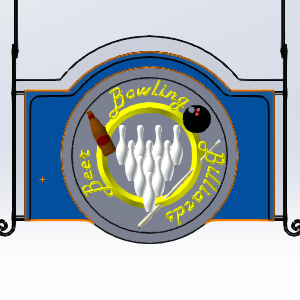
Part 18) Edit the MainBoard
SolidWorks does not support sketch pictures in assemblies. We you do load images into the assembly, although the images can still be vectorized, the images are invisible. Since we now need to bring in an image, and since we will need to position it visually, we will need to work in the individual part, rather than the overall assembly.
- In the Feature Manager Design Tree, right click MainBoard and select Edit Part.
The font of the MainBoard turns blue, and the other parts in the assembly become transparent showing a particular part is being edited.

Part 19) Load the Image
Now that the MainBoard is in Edit mode, we can import the image we will be vectorizing later in the tutorial.
- In the
 BobART Manager, right-click
  Images, and select Load Image.
The Image Location and Orientation dialog appears in the Property Manager. - Select the face shown in the image below.
The face is added to the Planar Face, Plane or Edge list. - Click OK.
The Open dialog appears. - Navigate to the location you saved the parts for the assembly, and select 3B_Logo.jpeg.
- Click Open.
Under Images, a new item  Image -3B_Logo is now available.
Part 20) Exit Edit Mode
Now that the image is loaded, we no longer need to be in part edit mode.
- In the Feature tab, click Edit Component.

The part is now out of edit mode, and the other components of the assembly become opaque once more.
Part 21) Reposition the Image
We will now position and size the image to get it in a good location.
- In the Feature Manager Design Tree, under MainBoard.sldprt, notice a Sketch has been added to the bottom.
Expand the new sketch. - Notice a Sketch Picture is under the Sketch.
Right-click the Sketch Picture and select Feature Properties.
The Sketch Picture dialog opens in the Property Manager.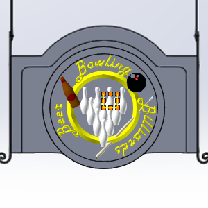
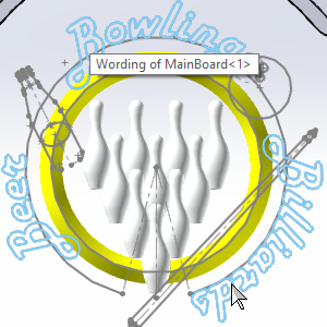
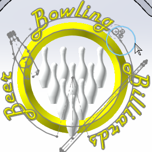
The location of the image is revealed. - Move your mouse over the location of the image, and notice your mouse switches to a pan icon.

Click and drag the image to the location shown in the following image.

Try to line up the top, and left sides of the image with the edges of the frame. - Once in position, hover over the bottom-right corner until the icon changes to scaling icon, then click and drag until it is the size seen in the image below.

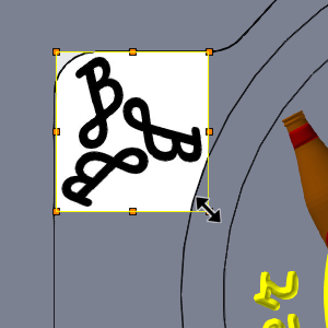
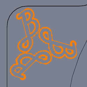
Notice each B in the logo is close to, but not touching, the edges of our parts. As you can see, being able to see the image is extremely helpful. If we would have brought this image into the overall assembly rather than through an edited part, this repositioning by sight, as we have done here, would be impossible. - Click OK.
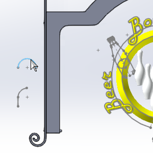
Part 22) Vectorize the Image
Vectorizing the image will provide us with the geometry needed to emboss the logo.
Vectorize the Image
- In the BobART Manager, under Images, right-click Image -3B_Logo and select Vectorize....
The Raster to Vector dialog appears. - Under Vectorize Strategy, set the Threshold Value to 200.
- Under Vectorize Parameters, leave the Accuracy: value at 0.8000.
- Select the With Splines check box, to add splines to the geometry.
- Click OK.

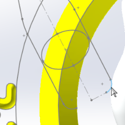
Tip: Notice we made the accuracy higher instead of lower, that is because the lower you go, the more the individual pixels are taken into consideration, as you can see in the image below.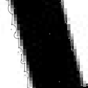
Test Another Result
- To test another level of accuracy, in the BobART Manager, under Image-3B_Logo, right-click
 Vectorization, and select Edit.
The Raster to Vector dialog launches again. - Under Vectorize Parameters, click in the Accuracy: field and type *2 behind the existing value of 0.8000, and press Tab.

This result looks a little better than our last, so we'll try to increase the accuracy value once more.
Test Another Result
- Right-click Vectorization, and select Edit.
- Add *2 to the accuracy value, and press OK.

Since this one isn't as good as the last one, we will change the value back.
Test Another Result
- Right-click Vectorization, and select Edit.
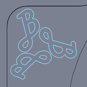
- Add /2 to the accuracy value.
- To test one last thing, clear the
 With Splines check box, to remove splines from the geometry.
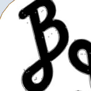
This geometry looks just a little bit cleaner, so we will leave the vectorization with these settings. - Right-click Image -3B_Logo and select Blank/Unblank.
The image disappears.
Part 23) Emboss the Logo
Now that we have the geometry we need from the vectorization, we can create an emboss feature for the logo with a basic Add application type.
Insert the Feature and Set the Parameters
-
Right-click
Emboss
Model, and click Emboss Regular. -
Change the Name to Logo.
- Click Color,
select white, and click OK.
In the Cross Section group, leave Convex ARC as the selected cross section.
Leave the Application Type, on Add. - In the Fast Edit group, set the Base Height to 0.7500.
- Click OK.
Select Feature Geometry
- Under Logo - Add, right-click Geometry,
and click
Re/Select.
-
In the Feature Design Tree, under MainBoard.sldprt, select our newly created Sketch at the bottom.
The geometry is added to the Re/Select Geometry list. - Click (OK).
Hide the Sketch
- In the Feature Design Tree,
under MainBoard.sldprt, right-click the Sketch and select Hide.
The sketch disappears.
Regenerate the Emboss Model
-
Right-click
Emboss
Model, and click Regenerate.
The emboss model is updated.
Part 24) Save the Logo as a Component
By saving this emboss as a component we can use it for the other side of our sign, and even for other projects in the future if we wish.
- Right-click Logo - Add, and select
Save as Component/STL.
The STL Save Option dialog appears. - Leave the default tolerance, but change the Reference Coordinate System to Local Art Model.
- Click OK.
The Save As dialog appears. - Select the folder the assembly is saved in, name the file LogoComponent, and click Save.
Part 25) Emboss from Component
With the component saved, we can now emboss from that component.
Insert the Feature and Select the Component
-
Right-click
Emboss
Model, and click Emboss from Component.
The Open dialog appears. - Navigate to, and select, LogoComponent.stl.
- Click Open.
The Create Emboss from Component dialog appears with the current model visible in the open GL window.
Set the Feature Parameters
- Change the Name to Right Logo.
- Click Color,
select white, and click OK.

- In the Origin group, change the values to : X: 16.3000, Y: 4.3500, Z: 0.7500.

- Click OK.
Regenerate the Emboss Model
-
Right-click
Emboss
Model, and select Regenerate.
The component is now visible on the Emboss Model.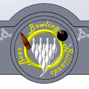

- Save the assembly.
This concludes the tutorial.